 DIRTY
A meter can show a healthy 24 V, 230 V or 400 V and still miss the fault. The contactor pulls in, chatters and drops out. A motor starts when it is cold but not after lunch. An LED driver resets as soon as another load comes on. Somebody changes the load, then the control module, and the fault is still there.
The missing test is often voltage drop under load.
A loose terminal, tired switch contact, corroded fuse holder or damaged conductor may pass enough current for a high-impedance meter to display the expected voltage. Ask the same path to carry working current and that small resistance starts consuming voltage. The circuit only tells the truth when it is doing the job that makes it fail.
This guide covers the method, not a particular installation standard. The examples include extra-low-voltage DC controls and low-voltage AC installations. Live testing on mains equipment is specialist work: it needs a justified method, competent people, suitable instruments and the controls required by local law and the site.
The idea in one line
Put the circuit under its normal load and measure across the section that should be carrying the current. The meter displays the voltage being lost in that section.
The reason is Ohm's law:
voltage drop = current × resistance
A resistance of 0.05 ohm looks harmless on paper. At 0.1 A it drops only 0.005 V. At 20 A it drops 1 V and dissipates 20 W as heat. The resistance did not change; the current made it visible.
That is why a resistance test on an isolated cable can be inconclusive. Ordinary multimeters do not reproduce the working current, terminal temperature, vibration or contact pressure. A joint may beep for continuity and still fail in service.
Before the probes come out
Start with the safest test that can answer the question. HSE guidance says electrical work should be carried out dead wherever possible and treats live fault-finding as live working. Electrical Safety First's current safe-isolation guide also makes a useful distinction: proving dead is a safety procedure, not just another voltage reading.
For work on mains circuits:
- decide whether a live measurement is genuinely necessary and permitted by the job procedure;
- identify the system, prospective fault level and measurement category before choosing the instrument;
- inspect the meter, leads, probe insulation, finger guards and connectors before use;
- use an instrument and leads with the correct CAT and voltage ratings for the point of measurement;
- follow the approved proving-unit or known-source procedure before and after an absence-of-voltage test;
- use the required PPE, barriers, insulated accessories and safe working position;
- keep fingers behind the probe guards; where the approved method permits clips, connect them with the circuit dead before re-energising for the measurement;
- never switch a meter through current or resistance ranges while it is connected to an energised voltage source.
OSHA requires test instruments and leads to be inspected before use and says only qualified persons may perform testing work on electric circuits or equipment. HSE's GS38 gives detailed guidance on suitable low-voltage test equipment, probes and leads. Those are good minimum checks even when a different national rulebook governs the job.
A non-contact detector is useful for an initial indication. It is not the instrument for measuring voltage drop, and it is not a substitute for the prescribed method of proving dead. Resistance and continuity functions belong on isolated, proved-dead and discharged circuits.
Record the fault before disturbing it
A useful test starts with the symptom, not the tool. Write down what the equipment is doing and what else is running when it happens. Heat, vibration and load sequence matter.
Capture four things if the job allows it:
- voltage at the source with the load off;
- voltage at the source with the load operating;
- voltage at the load while it is operating or trying to start;
- load current at the same moment.
If the source itself collapses, the fault may be upstream or the load may be drawing more current than expected. If the source holds but the load voltage falls, the loss is in the path between them. Without the current reading, it is easy to blame a cable for a drop caused by an overloaded or failing load.
For a fault that lasts only a fraction of a second, a meter's MIN/MAX capture, an inrush-capable clamp meter or a suitable logger is more useful than trying to watch changing digits. Check the instrument's capture time; a slow display can miss a short sag even when the electronics saw it.
Map the whole current path
Before measuring, sketch the circuit as a simple loop. For a DC control circuit it might be:
source positive → fuse → isolator → relay contact → connector → load → return conductor → source negative
For a single-phase AC load it may be:
source line → protective device → switch or contactor → load → neutral conductor → source neutral
Every connection is part of the circuit. The return path deserves the same attention as the supply path. A technician who checks only the positive or line side can replace half the panel before finding the poor negative or neutral connection that caused the fault.
Do not forget removable plugs, terminal blocks, crimp joints, fuse clips, contactor poles, local isolators and any cable that flexes. These are often more informative test points than the load itself.
A clean method for DC control circuits
On a 12 V or 24 V DC circuit, the basic test is easy to visualise. The following assumes the system is within the worker's competence and the manufacturer's service procedure allows energised testing.
Do not mistake extra-low voltage for low energy: batteries and DC buses can release destructive short-circuit current.
Check the positive side
Set the meter to DC volts. Connect one probe to the source positive terminal and the other to the load's positive terminal. Operate the load. The reading is the total drop in the positive path: cable, fuse, switches, contacts and connections.
Check the return side
Move the probes so the meter is connected between the load's negative terminal and the source negative terminal. Operate the load again. That reading is the drop in the return path.
Narrow it down
If one side shows an excessive drop, divide it into sections. Measure across the fuse holder, then the switch, then the contactor pole, then each connector or length of cable. Keep the same load operating for every comparison. When most of the total drop appears across one short section, the fault is there or immediately beside it.
This is quicker than disconnecting every joint and checking resistance. It also tests the circuit in the condition that creates the complaint.
Fluke gives automotive starting limits of 0.20 V across a wire or cable, 0.30 V across a switch and 0.10 V at a ground when manufacturer data are unavailable. Those figures belong to a particular 12/24 V troubleshooting context. They are useful clues, not universal acceptance limits for controls, vehicles or industrial machinery. The equipment manual and approved test plan win.
A worked example: the contactor that chatters
Suppose a 24 V DC contactor will not stay pulled in. The readings are:
| Measurement | Load off | Coil energised |
|---|---|---|
| Power supply terminals | 24.2 V | 23.9 V |
| Contactor coil terminals | 24.1 V | 18.7 V |
| Total positive-path drop | — | 5.0 V |
| Total return-path drop | — | 0.2 V |
The power supply is holding. The return path is not perfect, but it is not where most of the voltage has gone. The positive side is losing 5 V.
Measuring smaller sections with the coil energised shows 4.7 V across the fuse holder and only 0.3 V across the rest of the positive path. That points to the fuse clips or their terminations, not the coil. After isolating and proving dead, the technician finds heat-discoloured clips with weak contact pressure. The holder is replaced, the terminations are prepared and tightened to the manufacturer's value, and the same loaded test is repeated.
The important part is the final measurement. A repair is not proved by a clean-looking terminal. It is proved when the load works and the abnormal drop is gone under the same conditions.
The numbers in this example are illustrative. Coil operating limits and permissible circuit drop come from the actual equipment data.
Applying the method to AC circuits
The principle is unchanged, but the risk and the measurement plan are not. On 230/400 V installations, exposed live testing must be carried out only by a qualified person under the approved method for that system.
At the load, compare line-to-neutral voltage with the equipment stopped and operating. If the voltage falls only under load, check whether the same sag is present at the source. A stable source with a falling load voltage points toward the branch circuit. A source that sags at the same moment sends the investigation upstream or toward excessive load current.
Where the safe job method permits it, measure the loss across individual protective devices, contactor poles, isolators and conductor sections while current is flowing. Do not subtract readings taken several minutes apart and treat the result as a precise conductor drop; the supply and load may have changed between measurements. Use simultaneous logging or a direct measurement method appropriate to the installation when timing matters.
A neutral-to-earth reading can be useful evidence of load-related neutral drop, but it does not name the failed joint by itself. Bonding arrangement, parallel paths, harmonics and other loads can affect the reading. Trace the actual current path and measure it in sections.
On three-phase equipment, compare all phase-to-phase voltages and currents under the same operating condition. One low phase voltage may come from the supply, a fuse, a contactor pole or a termination. A large current imbalance with reasonably balanced supply voltage can point back toward the load. Variable-frequency drive outputs need instruments and methods designed for PWM waveforms; a normal multimeter reading at the drive output can be misleading.
Fluke's branch-circuit guidance makes the central point clearly: voltage drop depends on both circuit loading and source impedance. A reading without the load condition is only half a record.
When the meter shows a voltage that cannot do any work
A high-impedance digital multimeter can display capacitively coupled or “ghost” voltage on an open conductor. That reading may collapse when tested with an appropriate low-impedance function or approved two-pole tester.
Do not use that fact as permission to dismiss an unexpected voltage. First treat it as real. Identify the circuit and apply the correct proving procedure. Low-impedance modes are instrument-specific, can load sensitive electronic circuits and are not a substitute for the approved absence-of-voltage tester. Read the meter manual before using them.
What the pattern usually means
| What you observe | Likely direction | Next useful check |
|---|---|---|
| Correct voltage unloaded, low voltage at the load when running | High resistance in the supply or return path | Measure total supply-side and return-side drop separately |
| Source and load voltage fall together | Upstream supply problem or excessive load current | Record source voltage and current at the same instant |
| Most of the drop appears across a fuse or breaker | Poor clips, contacts, termination or damaged device | Isolate; inspect for heat damage and test the device to the approved procedure |
| Drop increases as the machine warms | Heat-sensitive joint, contact or conductor damage | Log drop and temperature through the operating cycle |
| Only the starting event fails | Starting current exposes resistance or source weakness | Use MIN/MAX, inrush capture or a suitable logger |
| Positive or line side is sound, return side is high | Poor negative, neutral or bonding-path connection | Divide the return path into sections |
| A strange voltage disappears on an appropriate LoZ test | Possible induced or ghost voltage | Confirm with the approved tester and safe-isolation method |
| Voltage is balanced but motor currents are not | Load, winding, connection or mechanical problem | Follow the motor and drive diagnostic procedure |
Repair the cause, not the reading
Once the bad section is identified, isolate the circuit and prove it dead before touching the connection. A loose terminal is not automatically fixed by leaning harder on the screwdriver. Inspect the conductor, ferrule or lug, terminal body, insulation and surrounding material for heat damage. Replace parts that have lost spring pressure, plating or mechanical integrity.
Use the manufacturer's conductor preparation and torque values. Do not tin flexible conductors unless the terminal is designed for it. Do not pack a damaged terminal with extra copper, bypass a protective device or add a parallel return lead without understanding the fault current and protection design.
Thermal imaging can help find a hot joint under load, but temperature depends on current, airflow, emissivity and time. A cool image at light load does not prove that the connection is sound. Use heat as another clue, then confirm electrically.
After the repair:
- repeat the same voltage-drop measurements with the same load;
- confirm the load voltage and current are within the equipment limits;
- run the equipment long enough to reproduce the original conditions;
- inspect for abnormal heating, noise, smell or discolouration;
- record the before-and-after readings and the repair made.
The field rule worth keeping
Do not ask only, “Is voltage present?” Ask, “How much voltage reaches the load while it is working, and where is the rest being lost?”
That question turns a parts-swapping job into a measured diagnosis. The meter is still just a tool. The useful work is choosing the right load condition, understanding the current path and proving the repair with the same test that exposed the fault.
References and original documents
This is an independent explanation, not a hands-on test or endorsement.
- Electrical Safety First — Best Practice Guide 2: Safe Isolation, Issue 4.3 — Current August 2026 guidance on managing electrical safety, proving dead and safe isolation on low-voltage installations.
- HSE — Electrical Test Equipment for Use on Low Voltage Electrical Systems (GS38) — Official guidance on live testing, suitable instruments, probes, leads and test equipment.
- OSHA — 29 CFR 1910.334: Use of Equipment — Requirements for qualified electrical testing and pre-use inspection of instruments, leads and probes.
- Fluke — Diagnosing Voltage Drops: Electrical Automotive Troubleshooting — Practical explanation of loaded-circuit voltage-drop testing, supply and ground paths, and automotive rule-of-thumb limits.
- Fluke — Guide to Digital Multimeter Safety — Measurement categories, voltage ratings, independent certification and inspection of meters and leads.
- Fluke — Power Quality Measurements at Receptacle Branch Circuits — Branch-circuit voltage drop, source impedance and the importance of measuring under load.
- Fluke — Dual Impedance Digital Multimeters — High- and low-impedance measurement, ghost voltage and limits on the use of LoZ functions.
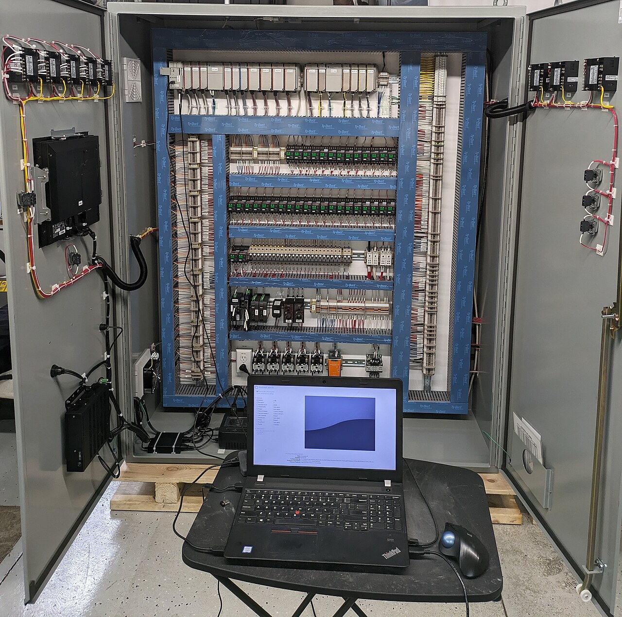
- Wikimedia Commons — Electrical Control Panel Being Testing By True Logic Group Inc. — Cover photograph by Jbarnard33, licensed CC BY 4.0.
This article is general fault-finding guidance for trained electrical workers, not a live-working procedure. De-energise wherever possible. Testing on exposed mains conductors must be justified, planned and carried out only by qualified people using the correct instrument, leads, PPE, barriers and local safe-working procedure. Follow the equipment manufacturer, installation standard and law that apply to the job.
Comments
Real experience is welcome here. Disagree with the article, the sources or another comment — keep it useful and respectful.
No comments yet. Start the discussion.